Особенности использования твердотельных реле
При использовании, практически, любых электрических цепей существует необходимость включения, или отключения электронных приборов, устройств, агрегатов и т.п. Используемое для этого оборудование относится к категории коммутационного оборудования, и включает в себя выключатели, рубильники, контакторы, реле и т.д.
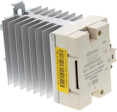
Одним из устройств, входящих в категорию коммутационного оборудования, являются твердотельные реле. Что же такое – твердотельное реле? Твердотельное реле – это устройство, построенное на полупроводниковых элементах и силовых ключах, таких, как симисторы, биполярные, или МОП-транзисторы. Также как и электромагнитные реле, предназначены они для управления слабым сигналом нагрузкой с большим напряжением, или током.
Твердотельные реле – уникальные устройства, которые после монтажа не требуют особого обслуживания. К примеру, они не нуждаются в очистке контактной группы, так как само понятие «контактная группа» отсутствует у твердотельных реле вообще. Преимущества твердотельных реле перед электромагнитными достаточно известны. Это и небольшие габариты, отсутствие шума и вибрации, продолжительный ресурс, отсутствие искрения, постоянное выходное сопротивление, которое не меняется в течение срока эксплуатации. Но есть у твердотельных реле и свои особенности применения, которые нельзя не учитывать при их эксплуатации. И вопросы в службу технической поддержки подтверждают это.
Блок-схема твердотельного реле с управлением постоянным током изображена на рисунке: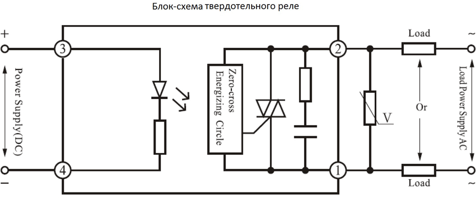
Как видно, управление реле осуществляется с помощью светодиода, установленного внутри корпуса реле. Сразу возникает вопрос – какое напряжение необходимо подать на вход реле, что оно «включилось», или «отключилось»? Для реле серии HHG1 управляющее напряжение указано как 3-32VDC. И с этим, как бы, вопросов не возникает. Но необходимо иметь в виду, что для «отключения» реле, управляющее напряжение надо отключать полностью. Согласно документации на это реле, напряжение отключения составляет 1VDC. То есть, при снижении управляющего напряжения от значения 3VDC до 1VDC, реле останется в открытом состоянии. А если принять во внимание возможное наличие электромагнитных «наводок» в цепи управления реле, то может возникнуть ситуация, что реле останется включенным постоянно.
Далее, нельзя проверить работоспособность реле, подключив к выходным контактам тестер, и «прозвонить» его. В отличие от электромагнитного реле, в котором коммутирующая цепь имеет всего два состояния – «замкнуто» и «разомкнуто» - твердотельные реле имеют силовые ключи, построенные на симисторах, или транзисторах. Проверить работоспособность твердотельного реле можно, собрав, простейшее устройство, изображенное на рисунке
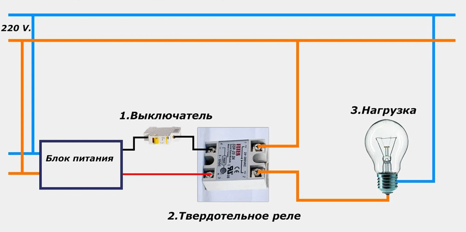 .
.
Кроме того, твердотельные реле имеют свои особенности для выбора нагрузки. При выборе твердотельного реле следует обращать особое внимание на нагрузочный ток. При эксплуатации твердотельного реле стоит учитывать не только рабочий ток, но также и токи, возникающие в процессе пуска, которые могут превышать номинальный параметр в несколько раз. Как правило, твердотельные реле выдерживают 10-кратную токовую перегрузку в течение 10 миллисекунд. Иначе говоря, при 10-кратной токовой перегрузке продолжительностью более 10 миллисекунд реле, практически, гарантировано выходит из строя.
Значения превышений максимального тока по отношению к номинальному отображены в таблице:
| Применение | Запас по току |
|---|---|
| Для ТЭНов | 30-40% больше номинального значения |
| Для асинхронных двигателей | 6-10 крат. |
| Для ламп накаливания | 8-12 крат. |
| Электромагнитные реле | 4-10 крат. |
Поэтому для твердотельных реле рекомендуется: для активной нагрузки (лампы, ТЭНы) запас по номинальному току в 2-4 раза. При пуске асинхронных двигателей, из-за большого пускового тока, запас по току нужно увеличить до 6-10 раз. Несколько снизить запас по току можно, предусмотрев пуск двигателя на холостом ходу с минимальными оборотами.
Немаловажным фактором при эксплуатации твердотельных реле является обеспечение теплового режима. Твердотельные реле способны проводить заявленный производителем ток при температурах не выше 40°С. При нагреве на каждые 10°С способность реле пропускать ток уменьшается на 20-25%. То есть, при температуре 80°С реле, практически, не способно пропускать ток.
И напоследок – для защиты твердотельного реле от выхода из строя вследствие короткого замыкания, нагрузку имеет смысл защитить установкой автоматических выключателей класса В.
Может показаться, что переход от обычных реле и контакторов на твердотельные реле слишком сложен. Действительно, такой переход требует более ответственного подхода. Но при правильном выборе твердотельного реле и обеспечения соответствующих условий его работоспособности, преимущества проявятся в первую очередь.