Трехфазные твердотельные реле для коммутации резистивной нагрузки серии HT
Нагревательные элементы, в том числе трубочные (ТЭН), наряду с другими типами нагрузки, могут подключаться к трехфазной сети с использованием трех основных схем соединений:
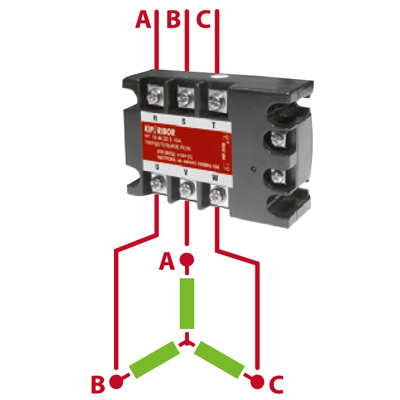
«Звезда»
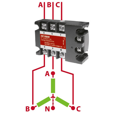
«Звезда с нейтралью»
«Треугольник»
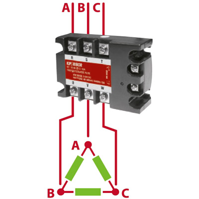
Для управления трехфазной нагрузкой при использовании одного твердотельного реле (ТТР) рекомендуется использовать схемы соединения нагрузки «звезда с нейтралью» (для случаев номинального рабочего напряжения нагрузки 220В) и «треугольник» (для случаев номинального рабочего напряжения нагрузки 380В). Схема соединения «Звезда без нейтрали» не рекомендуется к применению совместно с трехфазным ТТР, поскольку она не обеспечивает равномерности распределения нагрузки по фазам как в рабочем, так и в аварийном режимах.
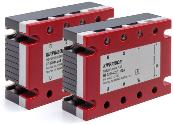
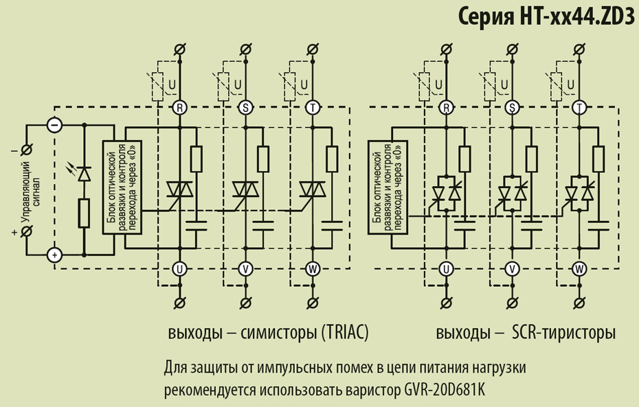
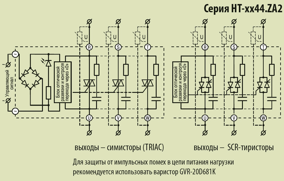
Трехфазные общепромышленные ТТР серии HT-xx44.ZD3 (управление постоянным током) и HT-xx44.ZA2 (управление переменным током) предназначены для коммутации трехфазных, либо трех однофазные цепей питания резистивной нагрузки. Реле обеспечивают одновременную коммутацию по каждой из трех фаз.
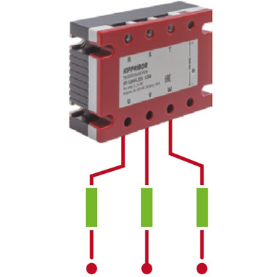
Схема подключения трех однофазных нагрузок
Надежная работа этих ТТР в заданном диапазоне токов обеспечивается следующими техническими решениями:
- Медное основание обеспечивает максимально эффективный отвод тепла от выходного силового элемента.
- Применение различных типов выходных силовых элементов (в зависимости от модификации) гарантирует высокую надежность ТТР.
- Встроенная шунтирующая RC-цепочка повышает надежность работы ТТР в условиях импульсных помех.
Твердотельные реле HT могут иметь (в зависимости от модификации) в качестве выходного ключа:
- симисторный выход (TRIAC) - для реле с током до 80А.
- SCR (триодный тиристор, или просто тиристор) выход - для реле с током 100А и выше.
SCR выход позволяет в значительной степени понизить тепловое сопротивление подложки реле и повысить характеристик теплоотвода. Реле такого типа ориентированы на работу в сложных эксплуатационных условиях при наличии быстрых переходных процессов в сети питания: работа в сети с больших уровнем помех, работа на индуктивную нагрузку, работа в условиях высоких скачков тока нагрузки.
При эксплуатации твердотельных реле необходимо учитывать, что рекомендуемые значения тока всегда будут ниже, чем справочные (указанные в обозначении ТТР).
Справочная таблица рекомендуемых токов нагрузки
| Управление переменным током | Управление постоянным током | Максимально допустимый ток нагрузки (справочно) | Рекомендуемый ток резистивной нагрузки (на каждую фазу) | I²t |
|---|---|---|---|---|
| HT-1044.ZA2 | HT-1044.ZD3 | 10А | 8А | 85А²с |
| HT-2544.ZA2 | HT-2544.ZD3 | 25А | 19А | 450А²с |
| HT-4044.ZA2 | HT-4044.ZD3 | 40А | 30А | 840А²с |
| HT-6044.ZA2 | HT-6044.ZD3 | 60А | 45А | 1800А²с |
| HT-8044.ZA2 | HT-8044.ZD3 | 80А | 60А | 3200А²с |
| HT-10044.ZA2 | HT-10044.ZD3 | 100А | 75А | 5000А²с |
| HT-12044.ZA2 | HT-12044.ZD3 | 120А | 90А | 7200А²с |
Кроме того, при отключении нагрузки, ТТР не обеспечивают полного размыкания электрической цепи, и выходные клеммы находятся под напряжением. Для полного отключения нагрузки (например, в период технического обслуживания оборудования) необходимо применять дополнительные меры по отключению цепи питания нагрузки, используя для этого контакторы, рубильники, выключатели нагрузки. При управлении индуктивной нагрузкой, параллельно цепи нагрузки необходимо установить варистор.
Схемы подключения ТТР
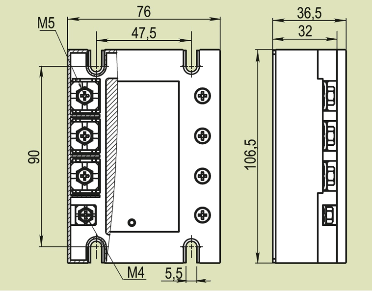
Габаритные и установочные размеры