Практические советы по выбору и использованию NTC термисторов компании TDK
Множество электрических и электронных устройств, таких как импульсные источники питания, электродвигатели или трансформаторы имеют значительные пусковые токи, возникающие при включении этих устройств, и которые могут привести к выходу из строя других компонентов или срабатыванию (отключению) автоматических выключателей защиты. Специально разработанные для ограничения пусковых токов, NTC термисторы компании TDK соединяются последовательно с нагрузкой, и позволяют существенно снизить эти токи. Особенностью NTC термисторов является высокое сопротивление в холодном состоянии. При протекании тока нагрузки через термистор, он разогревается, и его сопротивление уменьшается от 10 до 50 раз. Тем самым NTC термисторы позволяют управлять пусковым током более эффективно, чем резистор с фиксированным (постоянным) сопротивлением при той же мощности.
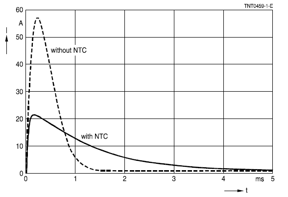 Влияние NTC термистора на пусковой ток в цепи постоянного тока
Термистор NTC типа всегда соединяется последовательно с нагрузкой. Пример простейшей защиты от пускового тока представлен на рисунке:
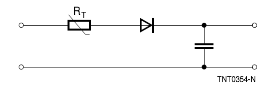 Базовая цепь защиты от пускового тока с NTC термистором
Если одного термистора NTC недостаточно для ограничения пускового тока, то последовательно устанавливаются два и более термисторов. Распараллеливание нескольких термисторов NTC недопустимо, так как ток нагрузки в этом случае будет распределяться неравномерно. Термистор, пропускающий наибольшую часть тока, будет нагреваться до тех пор, пока через него не пойдет весь возможный ток (что может привести к его разрушению), в то время как другие термисторы в параллельной цепи останутся холодными. Типовая схема защиты входной цепи от пускового тока, включая место альтернативной установки, представлена на рисунке:
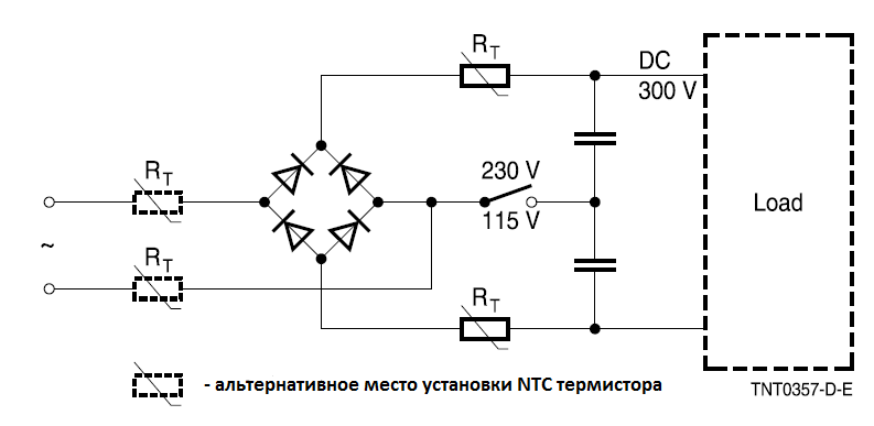 Типовая защита входной цепи с помощью NTC термисторов
Выбор наиболее подходящей серии и модели термистора NTC является предварительным условием для эффективной защиты цепи. Первым, и наиболее важным, критерием является максимальный ток при непрерывной работе, который определяется нагрузкой.
Самонагрев ограничителя пускового тока во время работы зависит от приложенной нагрузки. Несмотря на то, что некоторое количество тепла рассеивается, температура термистора NTC в крайних случаях может достигать среднего значения до 250°C. Тепло, выделяющееся во время работы, также будет рассеиваться через подводящие провода. Поэтому при монтаже термисторов NTC следует учитывать, что контактные поверхности также могут сильно нагреваться при максимальной нагрузке.
Возможности управления мощностью термистора NTC не могут быть полностью использованы во всем диапазоне температур. Приведенный ниже график зависимости тока от температуры предоставляет информацию о степени, в которой ток нагрузки должен быть уменьшен при определенной температуре окружающей среды (Ta). На примере NTC термисторов серий S237 и других:
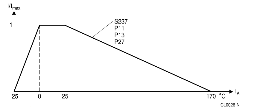 График зависимости тока от температуры для серий S237
Расчетное значение тока в процентах от максимального тока по графику для этих серий термисторов можно определить по формуле:
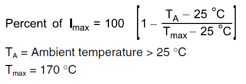 Расчетная формула тока в процентах от максимального тока, где Ta – температура окружающей среды, более 25°С.
Для NTC термисторов серий S153, S235, S236, S238, S364 график будет иметь зависимость с более широкими температурными пределами:
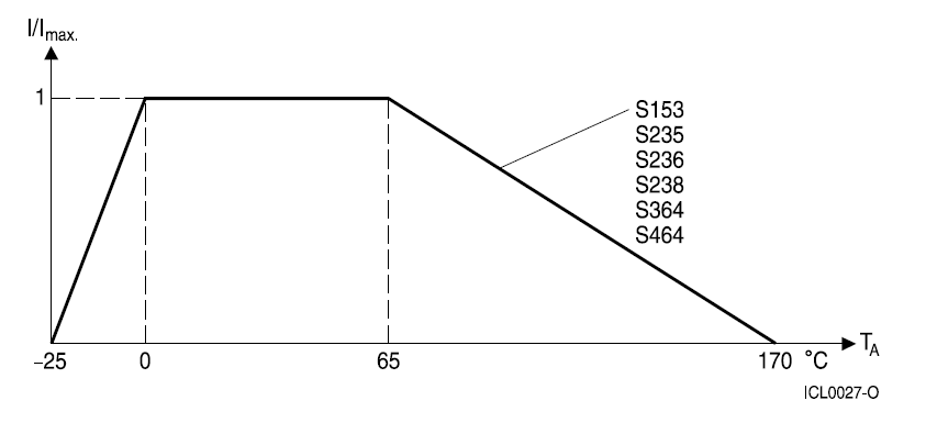 График зависимости тока от температуры для серий S153, S235, S236, S238, S364
Расчетное значение тока в процентах от максимального тока по графику можно определить по формуле:
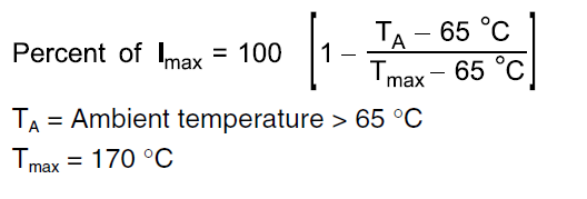 Расчетная формула тока в процентах от максимального тока, где Ta – температура окружающей среды, более 65°С.
Значение максимального тока Imax определено в Спецификации на серию NTC термисторов и обозначает максимально допустимый непрерывный ток (постоянный DC или среднеквадратичные значения RMS для синусоидального переменного тока AC) в диапазоне температур от 0°C до 65°C.
Когда нагрузка выключена, NTC термистор медленно остывает. Его сопротивление неуклонно возрастает, но полное значение сопротивления достигается только через 1-2 минуты (в зависимости от типа). Поэтому в некоторых приложениях может оказаться полезным предусмотреть цепь обхода (bypass) термистора для перезапуска. В этом случае, работа конечного устройства может быть возобновлена быстрее, и состояние термистора не повлияет на производительность системы.
Термисторы NTC типа компании TDK доступны в различных размерах и номинальных сопротивлениях, чтобы оптимально соответствовать конечному применению. Линейка продуктов варьируется от малогабаритного термистора серии S153 с максимальной мощностью 1.4Вт до самого большого в настоящее время термистора серии S464 с максимальной мощностью 6.7Вт. При этом максимальные непрерывные токи в цепях переменного тока AC могут быть до 20А.