Силовые промежуточные реле серии RS
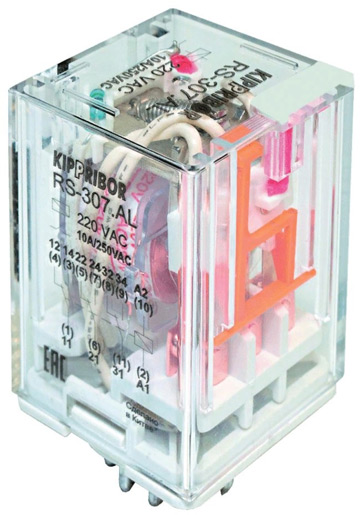
Силовые реле серии RS предназначены для коммутации как силовых цепей, так и цепей управления. Основным их отличием от большинства подобных реле является наличие специального цоколя, не позволяющего устанавливать данные реле на плату. Использование колодок с 11-контактным круглым разъемом позволяет осуществлять монтаж этих реле на DIN-рейку. Такая колодка гарантирует высокую надежность электрического контакта и прочную фиксацию реле в монтажной колодке. Специальная направляющая в центре круглого цоколя реле обеспечивает его безошибочную ориентацию при установке в колодку.
Контактная группа, состоящая из трех переключающих контактов, рассчитана на ток нагрузки до 10А (по AC-1). Реле серии RS оптимально подходят для коммутации такой нагрузки, как вентиляторы, катушки клапанов, циркуляционные насосы, нагревательные элементы и т.д.
К очевидным достоинствам реле серии RS можно также отнести наличие мощных силовых контактов, прозрачный корпус, позволяющий четко видеть состояние контактов, яркий светодиод индикации срабатывания реле, а также полная совместимость с реле данного типа других производителей, (в соответствии с ГОСТ 11152-82). В первую очередь это относится к реле Finder серии 60.13.
Реле серии RS имеют степень защиты IP40 – со стороны корпуса и IP00 – со стороны клемм.
Технические характеристики силовых реле KIPPRIBOR серии RS
| Характеристика | Значение |
|---|---|
| Время включения (при Uном) | не более 30 мс |
| Время выключения (при Uном) | не более 30 мс |
| Диапазон рабочих температур | –55...+70 °С |
| Относительная влажность | 35%...80% RH |
| Атмосферное давление | 86...106 кПа |
| Ударопрочность | 10g (длительность полуволны синусоиды ударного импульса 11 мс) |
| Ударопрочность | 10g (длительность полуволны синусоиды ударного импульса 11 мс) |
| Виброустойчивость | 10...55 Гц (удвоенная амплитуда 1,0 мм) |
| Масса | не более 17 г |
Электрические характеристики контактов
| Характеристика | постоянный ток (DC) | переменный ток (AC) |
|---|---|---|
| Номинальные ток и напряжение | 10 A при 28 В | 10 A при 250 В |
| Начальное сопротивление | не более 100 мОм | |
| Материал контакта | серебряный сплав (AgNi) | |
| Электрический ресурс | не менее 10⁵ | |
| Механический ресурс (при 300 вкл./мин) | не менее 10⁷ | |
| Электрическая прочность изоляции между группами контактов | ≥ 1500 VAC в течение 1 мин (ток утечки 1 мА) | |
Электротехнические характеристики катушки
| Характеристика | Постоянный ток (DC) | Переменный ток (AC) |
|---|---|---|
| Номинальное напряжение питания Uном | 24В | 220В |
| Напряжение включения (при 25°С), не менее | 0.8Uном | 0.8Uном |
| Напряжение выключения (при 25°С), не более | 0.10Uном | 0.30Uном |
| Предельное напряжение питания (при 25°С) | 1.10Uном | |
| Мощность | 1.5 Вт | 2.4 ВА |
| Электрическая прочность изоляции между контактами и катушкой | ≥ 1500 VAC в течение 1 мин (ток утечки 1 мА) | |
Габаритные размеры реле
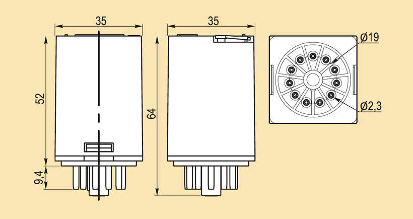
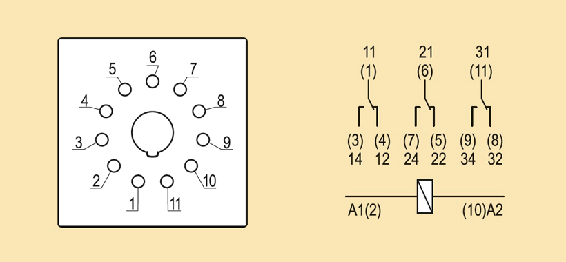
Схема подключения
К сожалению, параметром, ограничивающим широкое применение этих реле, является отсутствие широкой линейки номиналов управляющего напряжения.