Твердотельное реле постоянного тока RSCD

Основное назначение твердотельных реле (ТТР) – коммутация электрической цепи. Подобно обычному электромагнитному реле, ТТР позволяют небольшому управляющему сигналу включать или отключать гораздо больший ток нагрузки. Отсутствие движущихся частей позволяет значительно увеличить скорость срабатывания реле, а также сводит «на нет» механический износ внутренних компонентов. Наряду с очевидными различиями между твердотельным и электромагнитным реле, существуют и другие отличия, вызванные конструкцией устройства. Так, например, электромагнитное реле имеет возможность коммутировать цепи как переменного, так и постоянного тока. Твердотельное же реле переменного тока не сможет управлять нагрузкой постоянного тока. Равно, как и наоборот. Твердотельные реле для управления нагрузкой постоянного тока, недопустимо применять для управления цепями переменного тока.
Твердотельные реле постоянного тока, как уже стало понятно, используются только для переключения нагрузок постоянного тока. Ключевым преимуществом использования ТТР постоянного тока является то, что оно может выдерживать высокие пусковые токи, характерные для индуктивных нагрузок. ТТР постоянного тока используются, в основном, в качестве коммутационных компонентов для управления более мощными нагрузками, например, контакторами. Немаловажным параметром ТТР постоянного тока является и период управляющего сигнала. Значение его должно быть не менее, чем в 5 раз больше суммы времени включения, и времени выключения реле.
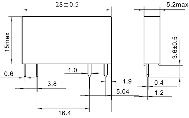
Реле постоянного тока серии RSCD предназначены для коммутации нагрузки постоянного тока с напряжением до 60В с нагрузкой 1А (реле RSCD06D1) И 3А (реле RSCD06D3). Реле имеют тонкий корпус толщиной 5,2мм. Конструкция реле позволяет использовать для их монтажа как печатный, так и навесной монтаж.
Габаритные размеры реле
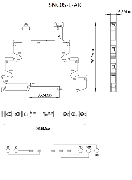
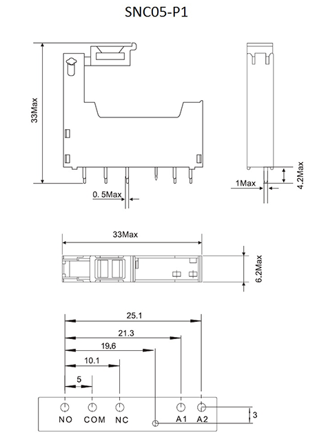
Для дополнительного удобства и большей технологичности монтажа можно использовать специальные колодки - SNC05-E-AR для монтажа на DIN-рейку, и SNC05-P1 для монтажа на печатную плату.
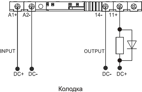
Габаритные размеры колодок и схема коммутации
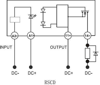
Типовая схема подключения реле RSCD
Основные технические характеристики реле RSCD
| Управляющее напряжение, VDC | 4…28 | |
| Напряжение открытия, VDC | 4 | |
| Напряжение отсечки, VDC | 1 | |
| Диапазон управляющих токов, мА | 6…20 | |
| Диапазон напряжения нагрузки, VDC | 5…60 | 3…60 |
| Однократное пиковое напряжение, VDC | 100 | |
| Номиналшьный ток нагрузки, А | 0,002…1 | 0,002…3 |
| Макс. время включения, ms | 1 | |
| Макс. время выключения, ms | 1 | |
| Однократный пиковый ток (10ms), А | 16 | 30 |
| Запас прочности по пику нагрузки, % | 40-60 | |