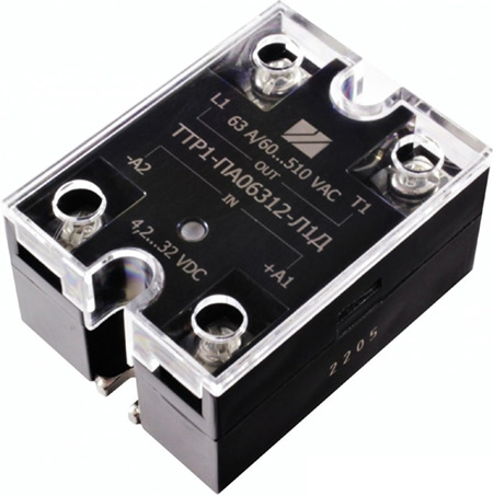
Твердотельные реле ТТР1-ПАххх-Л1Д для управления индуктивной нагрузкой
В системах современной автоматики все большее значение приобретают цепи и устройства коммутации. Что касается современных технологических областей, таких как системы связи, бытовая и промышленная автоматика, автомобильная электроника, то повсюду происходит постепенный, но явный переход от привычных схем коммутации на обычных электромагнитных реле к более надежным инструментам, таким как твердотельные реле (ТТР).
Полупроводники приходят на смену механическим устройствам коммутации и управления даже в цепях мощных токовых нагрузок. Однако, для правильной эксплуатации твердотельных реле необходимо четко разграничивать их применение для резистивной и индуктивной нагрузки. В случае использования реле для управления индуктивной нагрузкой необходимо учитывать переходные процессы в момент включения и выключения ТТР. И, несмотря на наличие во всех типах реле защитной цепи, все же имеются различные их модификации. Некоторые из твердотельных реле не допускают индуктивных нагрузок, другие же – специально для них приспособлены.
Скачок тока при управлении мощной нагрузкой активного характера обычно устраняется применением реле с переключением в нуле тока (переход «через ноль»). Но при управлении нагрузкой индуктивного типа, следует обеспечить более значительный запас по току.
Твердотельные реле ТТР1-ПАххх-Л1Д предназначены именно для управления индуктивной нагрузкой. Во-первых, защита от перенапряжения по выходу обеспечивается наличием защитных диодов. Во-вторых, что даже более важно, в отличие от реле с переходом «через ноль», коммутация происходит при максимальном значении выходного напряжения. Таким образом, пусковой ток сразу имеет максимальное значение с последующим снижением его амплитуды, что обеспечивает минимальную токовую перегрузку. Кроме того, SCR-выход (управляемый кремниевый выпрямитель, или SCR-тиристор) позволяет в значительной степени понизить тепловое сопротивление подложки реле и повысить характеристики теплоотвода.
Варианты управления мощностью в нагрузке
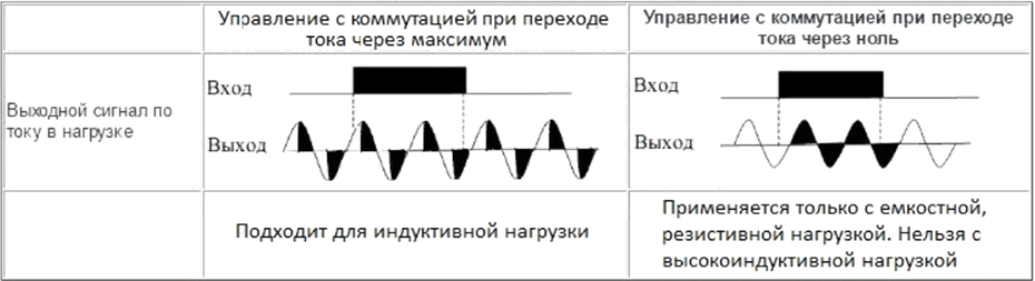
Однако, все это не исключает требования применения радиаторов и вентиляторов охлаждения для работы с большими токами коммутации. И совсем не следует забывать при выборе реле о необходимости обеспечения необходимого запаса по току.
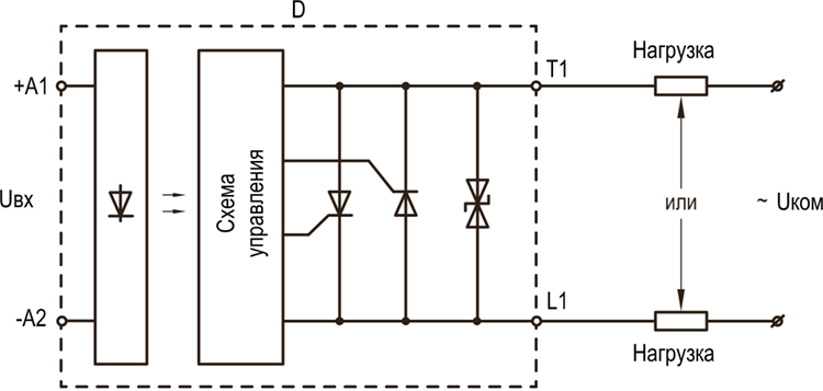
Схема включения реле
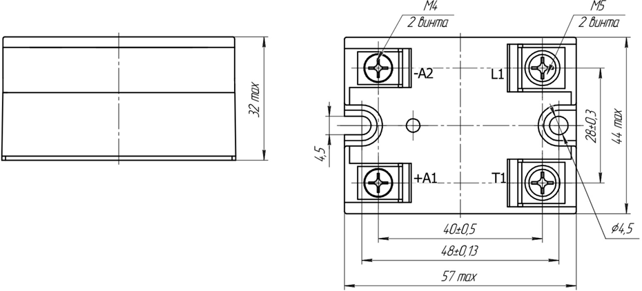
Габаритные размеры и посадочные места
Модификации реле и коммутируемый ток
| Модификация | Рекомендуемый режим | Предельно-допустимый режим |
|---|---|---|
| ТТР1-ПА02512-Л1Д | ~20 А | ~25 А |
| ТТР1-ПА04012-Л1Д | ~30 А | ~40 А |
| ТТР1-ПА06312-Л1Д | ~48 А | ~63 А |
| ТТР1-ПА08012-Л1Д | ~70 А | ~80 А |
| ТТР1-ПА10012-Л1Д | ~80 А | ~100 А |
| ТТР1-ПА12512-Л1Д | ~100 А | ~125 А |
Рекомендуемые режимы эксплуатации
| Наименование параметра, единица измерения | Обозначение | Значение параметра | |
|---|---|---|---|
| не менее | не более | ||
| Коммутируемое напряжение, среднеквадратичное значение, В | Uком | ~60 | ~420 |
| Входное напряжение во включенном состоянии, В | Uвх.вкл | 5 | 25 |
| Входное напряжение в выключенном состоянии, В | Uвх.выкл | 0 | 1 |
| Рабочий диапазон температур, °С | Tокр | -40 | 85 |