SI4925DDY-T1-GE3, Транзистор униполярный,МОП р-канальный, -30В, -8А, 5Вт, SO8
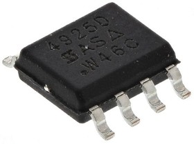
Изображения служат только для ознакомления,
см. техническую документацию
см. техническую документацию
1 350 ֏
от 5 шт. —
720 ֏
от 25 шт. —
580 ֏
от 100 шт. —
455 ֏
Добавить в корзину 1 шт.
на сумму 1 350 ֏

Описание
Integrated MOSFET Solutions
Vishay Integrated MOSFET Solutions combine components into a single monolithic chip to increase power density, increase efficiency, simplify design, and reduce Bill of Material (BOM) costs. These single- and multi-die MOSFETs integrate features such as Schottky Barrier diodes and ESD protection. These MOSFETs feature low ON-resistance N- and P-channel TrenchFET ® technologies and low thermal resistance.
Vishay Integrated MOSFET Solutions combine components into a single monolithic chip to increase power density, increase efficiency, simplify design, and reduce Bill of Material (BOM) costs. These single- and multi-die MOSFETs integrate features such as Schottky Barrier diodes and ESD protection. These MOSFETs feature low ON-resistance N- and P-channel TrenchFET ® technologies and low thermal resistance.
Технические параметры
| Channel Mode | Enhancement |
| Channel Type | P |
| Maximum Continuous Drain Current | 8 A |
| Maximum Drain Source Resistance | 41 mΩ |
| Maximum Drain Source Voltage | 30 V |
| Maximum Gate Source Voltage | -20 V, +20 V |
| Maximum Operating Temperature | +150 °C |
| Maximum Power Dissipation | 5 W |
| Minimum Gate Threshold Voltage | 1V |
| Minimum Operating Temperature | -55 °C |
| Mounting Type | Surface Mount |
| Number of Elements per Chip | 2 |
| Package Type | SOIC |
| Pin Count | 8 |
| Transistor Configuration | Isolated |
| Transistor Material | Si |
| Typical Gate Charge @ Vgs | 32 nC @ 10 V |
| Width | 4mm |
| Brand: | Vishay Semiconductors |
| Channel Mode: | Enhancement |
| Configuration: | Dual |
| Factory Pack Quantity: Factory Pack Quantity: | 2500 |
| Fall Time: | 12 ns |
| Forward Transconductance - Min: | 23 S |
| Id - Continuous Drain Current: | 8 A |
| Manufacturer: | Vishay |
| Maximum Operating Temperature: | +150 C |
| Minimum Operating Temperature: | -55 C |
| Mounting Style: | SMD/SMT |
| Number of Channels: | 2 Channel |
| Package / Case: | SOIC-8 |
| Part # Aliases: | SI4925DDY-GE3 |
| Pd - Power Dissipation: | 5 W |
| Product Category: | MOSFET |
| Product Type: | MOSFET |
| Qg - Gate Charge: | 32 nC |
| Rds On - Drain-Source Resistance: | 29 mOhms |
| Rise Time: | 8 ns |
| Series: | SI4 |
| Subcategory: | MOSFETs |
| Technology: | Si |
| Tradename: | TrenchFET |
| Transistor Polarity: | P-Channel |
| Transistor Type: | 2 P-Channel |
| Typical Turn-Off Delay Time: | 45 ns |
| Typical Turn-On Delay Time: | 10 ns |
| Vds - Drain-Source Breakdown Voltage: | 30 V |
| Vgs - Gate-Source Voltage: | -20 V, +20 V |
| Vgs th - Gate-Source Threshold Voltage: | 1 V |
| Automotive | No |
| Configuration | Dual Dual Drain |
| ECCN (US) | EAR99 |
| EU RoHS | Compliant |
| Lead Shape | Gull-wing |
| Maximum Continuous Drain Current (A) | 8 |
| Maximum Continuous Drain Current on PCB @ TC=25°C (A) | 7.3 |
| Maximum Diode Forward Voltage (V) | 1.2 |
| Maximum Drain Source Resistance (mOhm) | 29@10V |
| Maximum Drain Source Voltage (V) | 30 |
| Maximum Gate Source Leakage Current (nA) | 100 |
| Maximum Gate Source Voltage (V) | ±20 |
| Maximum Gate Threshold Voltage (V) | 3 |
| Maximum IDSS (uA) | 1 |
| Maximum Junction Ambient Thermal Resistance on PCB (°C/W) | 85 |
| Maximum Operating Temperature (°C) | 150 |
| Maximum Positive Gate Source Voltage (V) | 20 |
| Maximum Power Dissipation (mW) | 2500 |
| Maximum Power Dissipation on PCB @ TC=25°C (W) | 2.5 |
| Maximum Pulsed Drain Current @ TC=25°C (A) | 32 |
| Minimum Gate Threshold Voltage (V) | 1 |
| Minimum Operating Temperature (°C) | -55 |
| Mounting | Surface Mount |
| Operating Junction Temperature (°C) | -55 to 150 |
| Packaging | Tape and Reel |
| Part Status | Active |
| PCB changed | 8 |
| PPAP | No |
| Process Technology | TrenchFET |
| Product Category | Power MOSFET |
| Standard Package Name | SO |
| Supplier Package | SOIC N |
| Typical Diode Forward Voltage (V) | 0.75 |
| Typical Fall Time (ns) | 12|16 |
| Typical Gate Charge @ 10V (nC) | 32 |
| Typical Gate Charge @ Vgs (nC) | 32@15V|15@4.5V |
| Typical Gate Plateau Voltage (V) | 3.4 |
| Typical Gate to Drain Charge (nC) | 7.5 |
| Typical Gate to Source Charge (nC) | 4 |
| Typical Input Capacitance @ Vds (pF) | 1350@15V |
| Typical Output Capacitance (pF) | 215 |
| Typical Reverse Recovery Charge (nC) | 22 |
| Typical Reverse Recovery Time (ns) | 34 |
| Typical Reverse Transfer Capacitance @ Vds (pF) | 185@15V |
| Typical Rise Time (ns) | 8|35 |
| Typical Turn-Off Delay Time (ns) | 40|45 |
| Typical Turn-On Delay Time (ns) | 10|42 |
| Вес, г | 0.17 |


